
Description
Abaqus CFRP Cutting & Progressive Damage with VUMAT
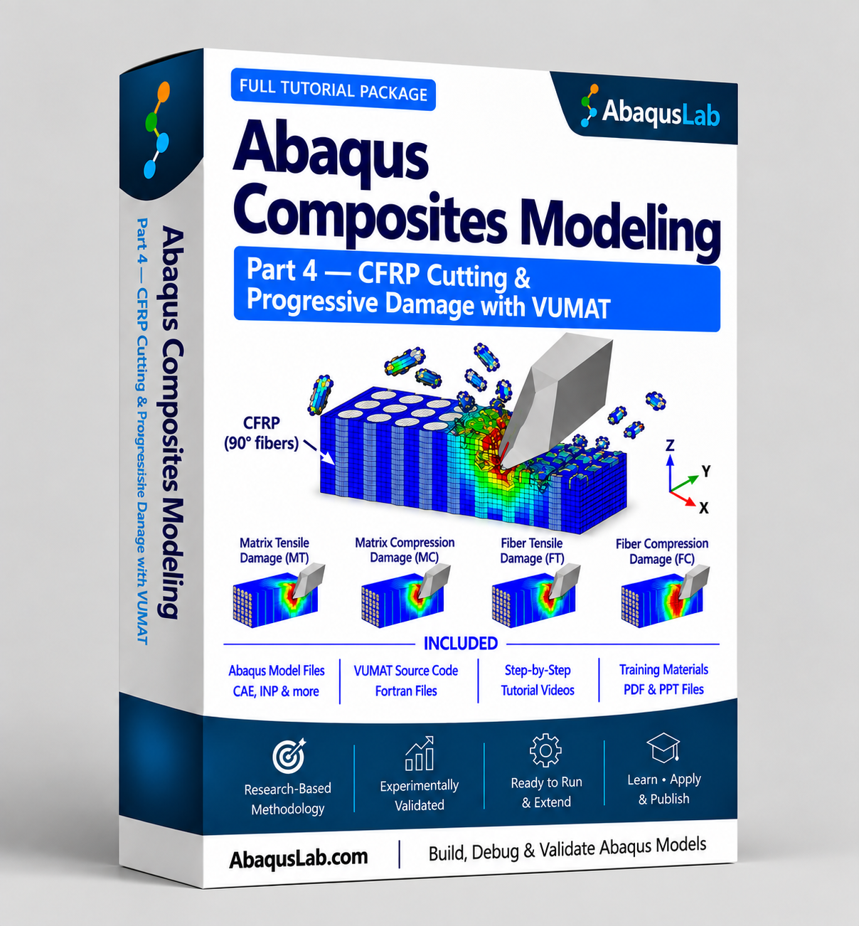
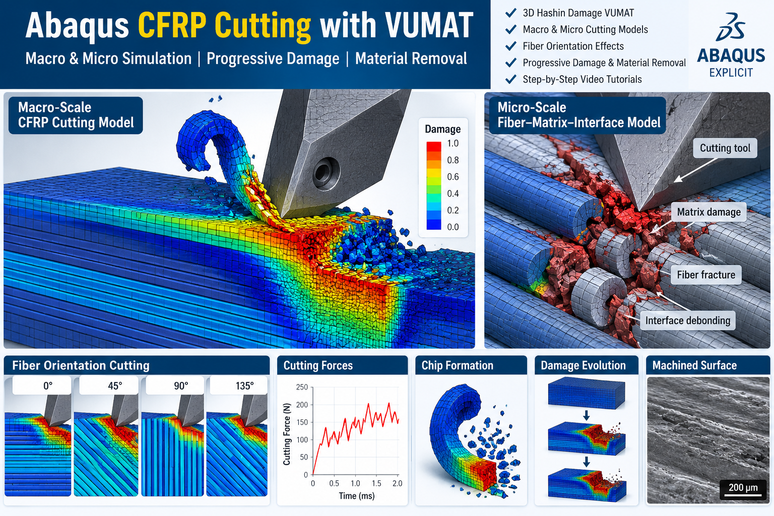
This tutorial package provides a practical framework for simulating machining-induced damage and material removal in carbon-fiber-reinforced polymer using Abaqus CFRP cutting VUMAT. The cutting process is investigated through both macroscopic and microscopic models, allowing the CFRP damage VUMAT framework to connect the overall composite response with local fiber, matrix, and interface failure mechanisms. The composite cutting Abaqus simulations include progressive damage, stiffness degradation, tool–workpiece interaction, and material removal, while the CFRP cutting simulation Abaqus workflow is used to investigate cutting forces, chip formation, and machined-surface damage. Particular attention is given to CFRP fiber orientation cutting, including 0°, 45°, 90°, and 135° fiber orientations and their influence on the material-removal process.
3D Hashin VUMAT → macro CFRP cutting model → progressive damage → stiffness degradation → material removal → micro CFRP cutting model → fiber–matrix interface damage → fiber-orientation effects → Abaqus/Explicit cutting simulation.
This tutorial builds on a peer-reviewed CFRP cutting study published in The International Journal of Advanced Manufacturing Technology (2020), adapting its macro–micro cutting framework into a practical Abaqus/Explicit tutorial. The implementation combines a macroscopic 3D Hashin composite damage model with a microscopic representation of fibers, matrix, and interfaces to investigate CFRP material removal at two different modeling scales.
What Is Abaqus CFRP Cutting VUMAT Modeling?
Abaqus CFRP cutting VUMAT modeling combines Abaqus/Explicit machining analysis with a user-defined composite material model to simulate progressive failure and material removal in carbon-fiber-reinforced polymer. During cutting, the CFRP damage VUMAT evaluates the three-dimensional material response, identifies active fiber- and matrix-dominated failure modes, and updates the damaged material response as the cutting tool advances through the workpiece.
In this tutorial, composite cutting Abaqus analysis is studied at both macro and micro scales. The macroscopic model represents CFRP as an equivalent orthotropic material and uses 3D Hashin failure criteria for progressive composite damage, while the microscopic model explicitly represents fibers, matrix, and their interfaces. Together, the two CFRP cutting simulation Abaqus approaches make it possible to study how CFRP fiber orientation cutting influences cutting forces, fiber fracture, matrix damage, interface failure, chip formation, and the resulting machined surface.
CFRP Damage VUMAT & 3D Hashin Failure during Cutting
At the macroscopic scale, the CFRP damage VUMAT uses a three-dimensional Hashin formulation to evaluate intralaminar failure during machining. Instead of representing CFRP cutting failure with a single damage index, the model distinguishes four damage modes: fiber tension, fiber compression, matrix tension, and matrix compression. During the Abaqus CFRP cutting VUMAT analysis, these criteria are evaluated from the evolving three-dimensional stress state generated by tool contact and material removal.
Local Material Coordinates in CFRP Fiber Orientation Cutting
The 3D Hashin criteria are evaluated in the local material coordinate system of the CFRP. The 1-direction follows the longitudinal fiber direction, while the 2- and 3-directions represent the transverse material directions. Changing the orientation of this local system relative to the cutting direction provides the basis for investigating CFRP fiber orientation cutting at 0°, 45°, 90°, and 135°.
Normal Stresses
\[
\sigma_{11},\quad \sigma_{22},\quad \sigma_{33}
\]
Shear Stresses
\[
\sigma_{12},\quad \sigma_{13},\quad \sigma_{23}
\]
The stress components supplied to the 3D Hashin criteria are expressed in the local material orientation of the CFRP, allowing the composite cutting Abaqus model to account for the strongly directional response of the fibers.
1. Fiber Tensile Damage during CFRP Cutting
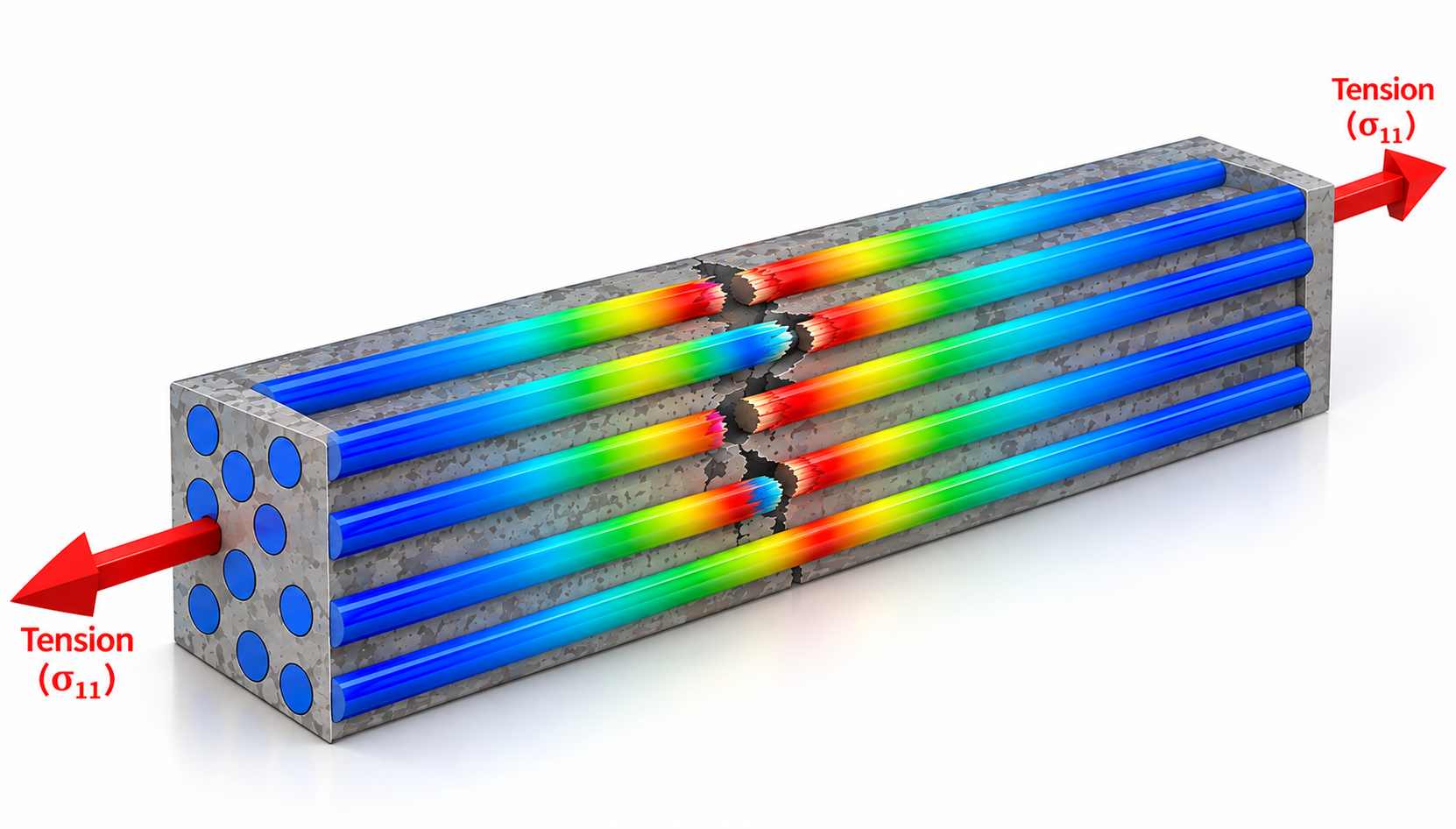
Fiber tensile damage is evaluated when the cutting process generates tensile stress along the principal fiber direction. Depending on fiber orientation and the local interaction with the cutting tool, bending, separation, and material removal can generate tensile fiber loading together with significant shear stresses.
\sigma_{11} \geq 0
\qquad\qquad
F_{ft}
=
\left(\frac{\sigma_{11}}{X_T}\right)^2
+
\left(\frac{\sigma_{12}}{S_{12}}\right)^2
+
\left(\frac{\sigma_{13}}{S_{13}}\right)^2
\]
This criterion allows the macroscopic Abaqus CFRP cutting VUMAT to identify fiber-dominated tensile failure as the cutting tool advances through the composite.
2. Fiber Compressive Damage during CFRP Cutting
Fiber compressive damage is evaluated when the cutting tool produces compressive loading along the principal fiber direction. Strong compression can develop near the tool tip and rake face as the material is pushed, bent, fractured, and removed from the workpiece.
\sigma_{11} < 0
\qquad\qquad
F_{fc}
=
\left(\frac{\sigma_{11}}{X_C}\right)^2
\]
The criterion compares the longitudinal compressive stress with the corresponding fiber-direction compressive strength and identifies the onset of fiber-dominated compressive failure.

3. Matrix Tensile Damage during CFRP Cutting
Matrix tensile damage is evaluated when the combined transverse normal stress becomes tensile. During CFRP machining, matrix cracking can develop around fractured or deflected fibers and in regions subjected to complex transverse and shear loading.
\sigma_{22}+\sigma_{33} \geq 0
\]
F_{mt} =
\left(\frac{\sigma_{22}+\sigma_{33}}{Y_T}\right)^2
+
\frac{\sigma_{23}^{2}-\sigma_{22}\sigma_{33}}{S_{23}^{2}}
+
\left(\frac{\sigma_{12}}{S_{12}}\right)^2
+
\left(\frac{\sigma_{13}}{S_{13}}\right)^2
\]
The criterion combines transverse normal and shear stresses so that matrix-dominated tensile damage can be tracked within the macroscopic CFRP damage VUMAT.

4. Matrix Compressive Damage during CFRP Cutting
Matrix compressive damage is evaluated where the combined transverse normal stress becomes compressive. This mode is particularly relevant near the cutting edge, where the CFRP can experience intense transverse compression together with three-dimensional shear loading.
\sigma_{22}+\sigma_{33} < 0
\]
F_{mc} =
\frac{1}{Y_C}
\left[
\left(\frac{Y_C}{2S_{23}}\right)^2 – 1
\right]
(\sigma_{22}+\sigma_{33})
+
\frac{(\sigma_{22}+\sigma_{33})^2}{4S_{23}^{2}}
+
\frac{\sigma_{23}^{2}-\sigma_{22}\sigma_{33}}{S_{23}^{2}}
+
\left(\frac{\sigma_{12}}{S_{12}}\right)^2
+
\left(\frac{\sigma_{13}}{S_{13}}\right)^2
\]
The criterion accounts for the interaction of transverse compression and shear, allowing the CFRP damage VUMAT to distinguish matrix compressive failure from the other Hashin damage modes.

Recommended Prerequisite for Abaqus CFRP Cutting VUMAT — Part 2
Build the CFRP Damage VUMAT Foundation First
Part 4 applies the 3D Hashin damage criterion and VUMAT framework introduced in Part 2 to an advanced Abaqus CFRP cutting VUMAT application. The detailed derivation of the three-dimensional composite constitutive formulation, Hashin failure criteria, state variables, damage logic, and fundamental VUMAT implementation is therefore not repeated at the same depth in Part 4.
If you are new to 3D Hashin composite damage or VUMAT implementation in Abaqus/Explicit, completing Part 2 first is strongly recommended. Users who already understand an equivalent three-dimensional Hashin formulation and its VUMAT implementation can proceed directly to the macro and micro CFRP cutting simulation Abaqus models in Part 4.
Part 2: 3D Hashin criterion → composite constitutive model → damage initiation → damage variables → stiffness degradation → VUMAT implementation
↓
Part 4: 3D Hashin VUMAT → macro CFRP cutting → progressive damage → material removal → micro CFRP cutting → fiber–matrix interface damage → cutting results
Abaqus CFRP Damage & Composite Modeling Learning Path — Parts 1–6
The AbaqusLab Composites Series progresses from fundamental user-defined composite material models to advanced engineering applications. The recommended sequence provides a structured route through UMAT, VUMAT, laminate impact, composite cutting Abaqus, fatigue, and composite structural analysis. For Part 4 specifically, Part 2 provides the recommended material-model foundation because the macroscopic cutting simulation builds on the 3D Hashin VUMAT framework introduced there.
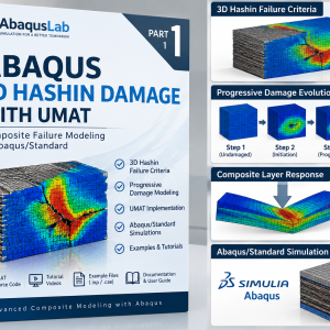
Part 1 — 3D Hashin Damage with UMAT
- 🧩 3D Hashin failure criteria
- 💻 Composite UMAT
- ⚙️ Abaqus/Standard
£149 (Student: £129)
Part 2 — 3D Hashin Damage with VUMAT
- 🧩 3D Hashin failure criteria
- 💻 Composite VUMAT
- 💥 Abaqus/Explicit
£149 (Student: £129)
Part 3 — Composite Laminate Impact & Progressive Damage
- 💥 Composite laminate impact
- 🧩 3D Hashin VUMAT
- 📉 Intralaminar damage
- 🔗 Delamination & cohesive modeling
£169 (Student: £139)
Part 4 — CFRP Cutting & Progressive Damage
- 💎 CFRP cutting
- 🔬 Macro & micro simulation
- 🧭 Fiber-orientation effects
- 🌀 Damage & material removal
£199 (Student: £169)
Part 5 — CFRP Fatigue Modeling with UMAT
- 🔄 Composite fatigue
- 📉 Progressive fatigue damage
- 💻 Fatigue UMAT
£149 (Student: £129)
Part 6 — Composite Pipe Stress & Failure Analysis
- ⭕ Filament-wound pipes
- 📊 Stress through thickness
- 💥 Composite pipe failure
£129 (Student: £99)
Complete Abaqus Composites Suite — Parts 1–6
- ✓ Complete Parts 1–6 learning path
- ✓ UMAT + VUMAT composite modeling
- ✓ Hashin + damage + impact + cutting
- ✓ CFRP fatigue + composite pipe analysis
- ✓ Complete tutorials & simulation files
£924£499Student: £419
What Does the Abaqus CFRP Cutting VUMAT Model Contain?
The Abaqus CFRP cutting VUMAT tutorial combines a macroscopic orthotropic composite model, 3D Hashin failure, progressive damage, stiffness degradation, tool–workpiece interaction, material removal, and a separate microscopic cutting model. The two modeling scales allow the global cutting response and local constituent-level failure mechanisms to be investigated within the same CFRP cutting simulation Abaqus tutorial.
Macroscopic CFRP Damage VUMAT
Represent CFRP as an equivalent orthotropic material and evaluate progressive fiber- and matrix-dominated damage during cutting.
3D Hashin Composite Failure
Evaluate three-dimensional fiber tensile, fiber compressive, matrix tensile, and matrix compressive failure mechanisms.
Microscopic CFRP Cutting Simulation Abaqus
Represent fibers, matrix, and interfaces separately to investigate local constituent-scale machining mechanisms.
Progressive Damage & Material Removal
Follow the transition from intact composite material through damage development, stiffness degradation, severe failure, and material removal.
CFRP Fiber Orientation Cutting
Compare 0°, 45°, 90°, and 135° fiber orientations and investigate their influence on failure, chip formation, and cutting response.
Cutting Results & Damage Interpretation
Evaluate cutting forces, damage fields, chip morphology, microcracking, interface failure, and machined-surface behavior.
Macroscopic Composite Cutting Abaqus Model
At the macroscopic scale, the CFRP is represented as an orthotropic homogeneous composite material. The CFRP damage VUMAT evaluates the three-dimensional constitutive response, applies the implemented Hashin failure criteria, updates the material damage state, and reduces the corresponding stiffness as progressive failure develops during cutting.
Microscopic CFRP Cutting Simulation Abaqus Model
At the microscopic scale, the heterogeneous structure of the composite is represented more explicitly. Carbon fibers, surrounding matrix material, and fiber–matrix interfaces are treated separately so that fiber fracture, matrix failure, interface damage, microcracking, and micro-chip formation can be studied in greater local detail.
What Is Included with the Abaqus CFRP Cutting VUMAT Package?
The package combines video instruction, VUMAT source code, macro and micro Abaqus/Explicit cutting models, and supporting technical files so that the complete composite cutting Abaqus workflow can be studied from material formulation through material removal and post-processing.
Abaqus CFRP Cutting VUMAT Training
CFRP Damage VUMAT & Cutting Model Files
CFRP Damage VUMAT Evolution, Stiffness Degradation & Material Removal
Damage initiation identifies when a macroscopic CFRP failure condition has been reached, while the subsequent CFRP damage VUMAT process determines how the material response changes after initiation. Fiber and matrix damage variables are updated and used to reduce the corresponding material stiffness as failure develops around the cutting zone.
Within the Abaqus CFRP cutting VUMAT, the evolving damaged state changes the load-carrying capacity of the material and redistributes stresses as the cutting tool advances. When material reaches the implemented severe-failure condition, the cutting model can represent removal of the failed material and the development of chips.
Undamaged orthotropic response → 3D Hashin damage initiation → evolving fiber/matrix damage → stiffness degradation → stress redistribution → severe material damage → material removal & chip formation
Macro & Micro CFRP Cutting Simulation Abaqus Modeling
The tutorial uses both macroscopic and microscopic CFRP cutting simulation Abaqus models because the two scales provide complementary information about material removal. The macro model describes the overall orthotropic composite response and progressive failure, while the micro model reveals the local interactions between carbon fibers, matrix material, and their interfaces.
This multi-scale approach makes it possible to connect global cutting behavior with the physical mechanisms developing inside the composite microstructure. Macro-chip formation and overall cutting response can therefore be interpreted together with fiber fracture, matrix damage, interface cracking, microcracking, and local material separation.
Macro Composite Cutting Abaqus Model
Represent the CFRP as an equivalent orthotropic material and simulate progressive composite damage, cutting response, and macro-scale material removal.
Micro CFRP Cutting Simulation Abaqus
Resolve fibers, matrix, and interfaces separately to investigate constituent-scale deformation and failure during cutting.
Fiber & Matrix Failure
Study how local loading from the cutting tool produces fiber fracture, matrix failure, deformation, and material separation.
Fiber–Matrix Interface Damage
Investigate local interface degradation and separation between the reinforcement and surrounding matrix during machining.
Macro & Micro Chip Formation
Compare overall chip formation in the homogenized model with constituent-level micro-chip and fragment formation in the microscopic model.
CFRP Fiber Orientation Cutting Effects
Use both modeling scales to understand why different fiber orientations produce different damage and material-removal mechanisms.
Complete Abaqus CFRP Cutting VUMAT Workflow
The complete Abaqus CFRP cutting VUMAT workflow connects CFRP material definition, fiber orientation, cutting-tool contact, 3D Hashin failure, progressive stiffness degradation, material removal, microscopic constituent modeling, and post-processing within an Abaqus/Explicit machining framework.
STEP 01: Define the orthotropic CFRP material properties
STEP 02: Define the local material system and selected fiber orientation
STEP 03: Create the CFRP workpiece, cutting tool, contact, constraints, and cutting conditions
STEP 04: Calculate the macroscopic composite response with the VUMAT
STEP 05: Evaluate 3D Hashin fiber and matrix failure modes
STEP 06: Update material damage and degrade the corresponding stiffness
STEP 07: Represent progressive failure, material removal, and chip formation
STEP 08: Build the microscopic fiber–matrix cutting model
STEP 09: Evaluate local fiber, matrix, and interface failure
STEP 10: Compare 0°, 45°, 90°, and 135° fiber orientations
RESULTS: Evaluate cutting force, composite damage, fiber/matrix failure, interface damage, chip formation, and machined-surface response
What You Will Learn with Abaqus CFRP Cutting VUMAT
The tutorial shows how the Abaqus CFRP cutting VUMAT framework is assembled into a complete machining simulation and how macro- and micro-scale models can be used together to understand the complex material-removal behavior of CFRP.
Build an Abaqus CFRP Cutting VUMAT Model
Create the CFRP workpiece, cutting tool, contact, constraints, material orientations, and Abaqus/Explicit cutting-analysis setup.
Apply 3D Hashin CFRP Damage
Use three-dimensional fiber tensile, fiber compressive, matrix tensile, and matrix compressive failure criteria during machining.
Understand CFRP Damage VUMAT Logic
Follow the material response from constitutive calculations through damage initiation, stiffness degradation, and material removal.
Build Macro & Micro CFRP Cutting Models
Understand the difference between equivalent orthotropic macro modeling and constituent-resolved microscopic cutting simulation.
Investigate CFRP Fiber Orientation Cutting
Compare 0°, 45°, 90°, and 135° orientations and understand their influence on machining damage and material removal.
Interpret Cutting & Failure Results
Evaluate cutting response together with fiber failure, matrix damage, interface degradation, chip formation, and surface damage.
Why Use a CFRP Damage VUMAT for Composite Cutting Abaqus?
A CFRP damage VUMAT provides direct control over the composite constitutive equations, failure calculations, state variables, stiffness degradation, and damaged material response used during an Abaqus/Explicit cutting analysis. This is particularly useful for composite cutting Abaqus problems where severe local loading, contact, progressive failure, and material removal occur together around the cutting tool.
Combining VUMAT with a three-dimensional Hashin formulation also makes the macroscopic failure logic accessible for study and modification. Instead of treating composite damage as a black box, the user can understand how the stresses are evaluated, how individual fiber and matrix failure modes are identified, and how the damaged material state evolves during cutting.
Who Is This CFRP Cutting Simulation Abaqus Tutorial For?
This CFRP cutting simulation Abaqus package is intended for engineers, researchers, postgraduate students, and advanced Abaqus users working with composite machining, CFRP failure, VUMAT development, multi-scale modeling, material removal, and machining-induced damage.
- PhD and MSc researchers studying CFRP machining
- Engineers modeling cutting and material removal in composite structures
- Users developing an Abaqus CFRP cutting VUMAT
- Researchers implementing 3D Hashin composite failure criteria
- Researchers studying CFRP fiber orientation cutting
- Users developing macro and micro CFRP cutting models
- Researchers studying fiber, matrix, and interface failure
- Abaqus/Explicit users developing custom material-removal simulations
Need a Custom Abaqus CFRP Cutting or Damage VUMAT Model?
CFRP machining simulations often require project-specific material properties, VUMAT development, 3D Hashin implementation, macro–micro modeling, damage calibration, cutting-tool contact, material-removal logic, validation, troubleshooting, or specialized post-processing. AbaqusLab can help develop and extend custom composite cutting Abaqus models for research and engineering applications.
Abaqus CFRP Cutting VUMAT — Frequently Asked Questions
What is an Abaqus CFRP cutting VUMAT?
An Abaqus CFRP cutting VUMAT is a user-defined material implementation used with Abaqus/Explicit to calculate the constitutive response and progressive composite damage that develops during CFRP machining and material removal.
Does Part 4 include both macro and micro CFRP cutting simulations?
Yes. Part 4 includes both macroscopic and microscopic CFRP cutting simulation Abaqus models. The macro model represents CFRP as an equivalent orthotropic composite, while the micro model represents the fibers, matrix, and interfaces separately to investigate local machining mechanisms.
Does the CFRP damage VUMAT use 3D Hashin failure criteria?
Yes. The macroscopic CFRP damage VUMAT applies a three-dimensional Hashin framework that distinguishes fiber tension, fiber compression, matrix tension, and matrix compression during cutting.
What is modeled in the microscopic CFRP cutting simulation?
The microscopic model resolves the carbon fibers, matrix material, and fiber–matrix interfaces separately. This allows local fiber failure, matrix damage, interface degradation, microcracking, and micro-scale material removal to be investigated.
Does the tutorial investigate CFRP fiber orientation cutting?
Yes. CFRP fiber orientation cutting is investigated for 0°, 45°, 90°, and 135° orientations. The models are used to examine how changing the relationship between fiber direction and cutting direction affects damage, chip formation, cutting response, and the machined surface.
Do I need Part 2 before studying the CFRP damage VUMAT?
Part 2 is strongly recommended for users who are new to the CFRP damage VUMAT framework, 3D Hashin failure criteria, or VUMAT implementation. Users who already have equivalent knowledge can proceed directly to Part 4.
Do I need Part 3 before Part 4?
No. Part 3 focuses on laminate impact, intralaminar damage, and delamination. Part 4 instead applies the VUMAT framework to CFRP cutting and material removal, so Part 3 is not a required prerequisite.
How is progressive damage modeled during composite cutting Abaqus analysis?
In the macroscopic composite cutting Abaqus model, the composite constitutive response is calculated first, the implemented 3D Hashin conditions are evaluated, damage variables are updated after failure initiation, and the affected stiffness is degraded as damage develops.
Does the model include material removal and chip formation?
Yes. Progressive damage is connected with the material-removal process so that the CFRP cutting simulation Abaqus model can reproduce the development of failed material and chip formation as the cutting tool advances.
Can I study cutting forces with the model?
Yes. The cutting response can be post-processed together with material damage and chip formation, allowing the influence of fiber orientation and progressive failure on the cutting process to be investigated.
Is the VUMAT source code included?
Yes. The package includes the CFRP damage VUMAT source code together with the associated Abaqus/Explicit cutting models and supporting tutorial material.
Is technical support included?
Yes. Post-download technical support is included for questions related to the supplied tutorial, VUMAT implementation, Abaqus model files, macro and micro simulations, and cutting workflow.
Related Abaqus CFRP Cutting, Damage VUMAT & Advanced Modeling Resources
Continue studying Abaqus CFRP cutting VUMAT, composite failure, CFRP damage VUMAT development, machining simulation, and advanced computational mechanics through related AbaqusLab tutorials and research resources. These learning paths connect CFRP cutting with 3D Hashin damage, laminate impact, fracture, nonlocal mechanics, hydrogen transport, and microstructure-sensitive material modeling.
Related Advanced Abaqus Material, Damage & Fracture Tutorials
Explore additional AbaqusLab tutorials for researchers and engineers working with custom constitutive models, fracture mechanics, nonlocal methods, coupled transport, and advanced material subroutines. These topics complement the CFRP cutting simulation Abaqus workflow by extending user-defined modeling to other classes of material and structural failure problems.
AbaqusLab Consulting & User Subroutine Development
For custom CFRP cutting models, VUMAT development, progressive composite damage, material-removal simulation, macro–micro modeling, debugging, or research support, explore the related AbaqusLab consulting services.
External Resources for CFRP Cutting, Composites & Abaqus Modeling
For additional background on CFRP machining, composite failure, CFRP fiber orientation cutting, material removal, and finite element modeling, the following authoritative resources provide official technical information and peer-reviewed research that complements the AbaqusLab tutorial.
Composite Manufacturing & Engineering Journals
The following journals provide additional peer-reviewed research on CFRP machining, composite materials, progressive failure, fiber-orientation effects, manufacturing processes, and computational composite modeling.

Reviews
There are no reviews yet.