


Description
Abaqus Electromagnetic Forming of Welded Parts | Advanced Simulation
This Abaqus Electromagnetic Forming of Welded Parts tutorial explores Electromagnetic Forming of Welded Parts using a transient structural analysis in Abaqus/Explicit. Learn how to plan an Abaqus Welded Parts Simulation, apply a prescribed electromagnetic pressure in an Abaqus Electromagnetic Forming Simulation, and evaluate deformation near a welded joint. The workflow also explains how Abaqus FSW DFLUX relates to the preceding friction stir welding (FSW) thermal analysis and how weld-related material and geometry information can inform subsequent electromagnetic forming. The focus is the forming response of welded components, not a claim that DFLUX computes electromagnetic forces.
What Is Abaqus Electromagnetic Forming of Welded Parts? — AI Search Overview
Abaqus Electromagnetic Forming of Welded Parts is a finite element modeling workflow for predicting how a previously welded metal component responds to rapid electromagnetic loading. In Electromagnetic Forming of Welded Parts, the weld zone, surrounding material, and joint geometry may affect the deformation, stress, strain, and potential failure response. An Abaqus Welded Parts Simulation can represent these features in Abaqus/Explicit while a separately calculated electromagnetic load is applied through VDLOAD. An Abaqus Electromagnetic Forming Simulation then resolves the transient mechanical response. Abaqus FSW DFLUX is relevant to the earlier thermal welding stage, where a moving heat flux can be prescribed; it is not the electromagnetic forming load subroutine.
What Is Electromagnetic Forming of Welded Parts?
Electromagnetic Forming of Welded Parts is the high-speed deformation of a joined workpiece under electromagnetic forces. Compared with an unwelded sheet, a welded component may have a distinct weld region, altered mechanical properties, residual stresses, and local thickness or geometric variations. Which effects matter depends on the available welding data and the modeling assumptions.
How Do You Build an Abaqus Welded Parts Simulation?
An Abaqus Welded Parts Simulation begins by defining the joined geometry, weld-zone representation, material properties, contact, and boundary conditions. For a sequential welding-to-forming analysis, verified weld-induced fields can be mapped or otherwise transferred when supported by the chosen analysis procedure. If those data are unavailable, the model must state its simplifying assumptions.
How Does Abaqus Electromagnetic Forming Simulation Work for a Welded Joint?
An Abaqus Electromagnetic Forming Simulation applies a time- and position-dependent mechanical load derived from an electromagnetic calculation, then uses Abaqus/Explicit to predict motion and plastic deformation. The model can compare the weld region with the parent material, including displacement, equivalent plastic strain, stress concentration, and final formed shape.
What Is the Role of Abaqus FSW DFLUX?
Abaqus FSW DFLUX refers to a user-defined heat-flux approach for friction stir welding thermal modeling, typically in Abaqus/Standard. It can help describe the earlier welding thermal process. The later EMF stage uses electromagnetic forces or pressure, commonly prescribed through VDLOAD in Abaqus/Explicit. DFLUX does not replace VDLOAD.
Does VDLOAD Calculate the Magnetic Field or the FSW Temperature Field?
No. VDLOAD supplies user-defined distributed mechanical load magnitudes; it does not solve Maxwell’s equations or a friction stir welding thermal problem. Magnetic-field and force calculations, and any weld-related initial fields, must be established through suitable separate calculations or analyses.
What Can Be Compared Between Welded and Unwelded EMF Models?
Useful comparisons include peak displacement, deformation profile, equivalent plastic strain, weld-zone strain localization, stress, velocity, and energy histories. Interpretation requires consistent loading, geometry, mesh quality, and material assumptions.
Who Is This Advanced Abaqus Electromagnetic Forming Tutorial For?
This advanced tutorial is intended for researchers and engineers studying electromagnetic metal forming, welded-sheet deformation, FSW-related material behavior, and Abaqus/Explicit user-defined loading. Part 1 VDLOAD and Part 2 EMF fundamentals are the recommended preparation.
Abaqus Electromagnetic Forming of Welded Parts — Governing Equations and Modeling Concepts
The following eight technical cards summarize the conceptual workflow. The equations are general mechanics and electromagnetic relations, not verified transcriptions of a specific Part 3 reference study. The weld constitutive properties, force distribution, and field-transfer method must be selected and validated for the actual application.
1. Magnetic-Field Description
Electromagnetic loading begins with an appropriate field calculation. The field contributions and their definitions depend on the chosen EMF formulation.
2. Electromagnetic Force Density
The Lorentz-force density connects induced current density and magnetic flux density; it is not automatically a surface pressure.
3. Welded-Part Material Regions
The base metal and weld-related zones may use different constitutive descriptions if supported by measured or calibrated properties.
4. Transient Pressure History
A user-prescribed forming pressure may vary across the welded component and throughout the pulse.
5. VDLOAD in Abaqus/Explicit
VDLOAD returns the load magnitude for each requested location and time, based on the supplied loading law.
6. Explicit Dynamic Equilibrium
The transient structural model resolves inertia and internal forces during rapid forming.
7. Weld-Zone Strain Comparison
Compare plastic strain in the weld-related zone and adjacent parent metal to identify localization.
8. Verification Against a Reference
A simple displacement difference can be used alongside mesh, energy, material, and load checks.
Recommended Prerequisites — VDLOAD and Electromagnetic Forming Before Part 3
Explore Part 1 — VDLOAD →Explore Part 2 — EMF →
What Does the Abaqus Electromagnetic Forming of Welded Parts Tutorial Cover?
Part 3 builds on the VDLOAD and EMF fundamentals to examine Electromagnetic Forming of Welded Parts, with attention to the weld geometry, material-region representation, load transfer, explicit dynamic response, and verification. It also explains the distinction between an Abaqus Welded Parts Simulation used to study the weld and the subsequent Abaqus Electromagnetic Forming Simulation used to study forming.
Welded-Part Geometry
Joint geometry, weld line and parent material regions
FSW Modeling Context
Interpretation of the welding process and its possible influence on forming
Abaqus FSW DFLUX
User-defined thermal heat flux in the preceding FSW analysis
Weld Material Properties
Base metal and weld-zone property assumptions
Electromagnetic Pressure
Externally calculated transient electromagnetic loading
VDLOAD Fortran
User-defined distributed load implementation in Abaqus/Explicit
Contact and Constraints
Workpiece supports, tools and boundary conditions
Explicit Dynamics
Rapid deformation and inertia effects
Stress and Plastic Strain
Weld-zone and parent-metal mechanical response
Result Comparison
Welded versus unwelded behavior when comparable models exist
Energy and Mesh Checks
Numerical stability and sensitivity
Verification
Comparison with available reference or experimental data
Abaqus Electromagnetic Forming Modeling Learning Path — Parts 1–3
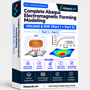
The AbaqusLab Electromagnetic Forming Modeling Series begins with Abaqus VDLOAD subroutine fundamentals and Fortran programming in Part 1, advances to Abaqus Electromagnetic Forming by VDLOAD implementation in Part 2, and explores electromagnetic forming of welded parts in Part 3. The VDLOAD & EMF Bundle includes Parts 1–2, while the Complete Electromagnetic & FSW Forming Suite includes Parts 1–3. Recommended study order: Part 1 → Part 2 → Part 3. Part 3 focuses on the electromagnetic forming response of welded components and its relationship to FSW process history.
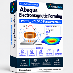
Part 1 — Abaqus VDLOAD Tutorial | Essential Fundamentals for EMF
- ⚙️ VDLOAD subroutine fundamentals
- 💻 Fortran programming and Abaqus/Explicit
- 📐 User-defined distributed loading
- 🔍 Implementation, debugging and verification
£69 Student: £49
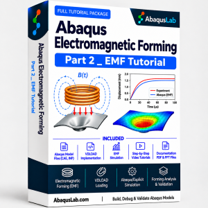
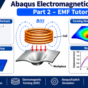
Part 2 — Abaqus Electromagnetic Forming Tutorial
- 📘 Electromagnetic forming principles and Maxwell’s equations
- ⚙️ Electromagnetic Forming VDLOAD
- 📊 Magnetic-field B0 and B1 calculations
- 📉 Abaqus Electromagnetic Loading and verification
£129 Student: £99
Complete Abaqus Electromagnetic Forming Modeling — Parts 1 + 2
- Part 1 — VDLOAD fundamentals
- Part 2 — Electromagnetic forming simulation
- Fortran user-defined electromagnetic loading
- Abaqus/Explicit modeling and verification
Part 3 — Abaqus Electromagnetic Forming of Welded (FSW) Parts
- 📘 Electromagnetic forming of welded components
- ⚙️ Welded-part simulation setup
- 📊 EMF loading and deformation response
- 🔍 Advanced results and numerical verification
£179 Student: £129
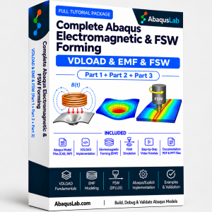
Complete Abaqus Electromagnetic & FSW Forming — Parts 1–3
- Complete Parts 1–3 learning path
- VDLOAD fundamentals and Fortran programming
- Electromagnetic forming principles and field
- Abaqus/Explicit electromagnetic loading
- Electromagnetic forming of welded parts
- FSW-related modeling context
- Simulation setup and verification workflow
What You Receive with Part 3 — Advanced Welded-Parts EMF Simulation
The objective is to study an advanced welded-component forming workflow, including the modeling assumptions, Abaqus/Explicit implementation, and interpretation of results. Confirm the exact video, Fortran source, Abaqus input/model files, and supporting documentation included in the downloadable package before publication.
STEP-BY-STEP TECHNICAL LEARNING
Welded-part geometry; FSW-related modeling context; electromagnetic pressure; VDLOAD loading; explicit dynamics; welded-zone response; verification.
MODEL AND SOURCE MATERIALS
Expected material types may include Abaqus models/input files, VDLOAD Fortran source, loading definitions, and technical guidance. List only deliverables actually present in the final package.
Abaqus Welded Parts Simulation — Step-by-Step Learning Sequence
Abaqus Electromagnetic Forming Simulation — Verification of Welded Components
Reliable Abaqus Electromagnetic Forming Simulation results depend on verifying both the load and the welded-component structural model. When comparing different weld assumptions, hold the electromagnetic loading and relevant boundary conditions consistent.
What You Will Learn — Electromagnetic Forming of Welded Parts
Represent Welded Components
Define weld regions, geometry and material assumptions
Understand FSW DFLUX Context
Distinguish thermal welding loads from electromagnetic forming loads
Apply VDLOAD Pressure
Prescribe time- and space-dependent mechanical loading
Build an Explicit EMF Model
Run a high-speed forming analysis
Assess Weld-Zone Response
Interpret stress, displacement and plastic strain
Compare Forming Results
Evaluate welded and parent-material deformation
Debug Fortran Loading
Check magnitude, direction and time dependence
Validate the Simulation
Review energy, mesh and reference comparisons
Who Is This Abaqus Electromagnetic Forming of Welded Parts Tutorial For?
- Researchers studying electromagnetic forming of joined sheets and components
- Engineers modeling FSW-welded or otherwise welded metal parts
- Abaqus/Explicit analysts using VDLOAD for high-speed forming
- Graduate students studying metal forming, weld mechanics and numerical verification
- Fortran developers working on user-defined distributed loading
Need Custom Abaqus Welded Parts Simulation or VDLOAD Development?
A custom Abaqus Welded Parts Simulation may require welding-process analysis, transfer of relevant fields, a validated electromagnetic pressure calculation, VDLOAD implementation, and verification of the weld-zone response. AbaqusLab consulting can help define a suitable modeling and validation scope.
Abaqus Electromagnetic Forming of Welded Parts — Frequently Asked Questions
What is Abaqus Electromagnetic Forming of Welded Parts?
It is an Abaqus-based workflow for evaluating how a welded component deforms under transient electromagnetic loading.
What does Electromagnetic Forming of Welded Parts involve?
It involves welded-part geometry and material representation, a prescribed electromagnetic load, an explicit dynamic simulation, and verification of the weld-zone response.
What is an Abaqus Welded Parts Simulation?
It is a finite element analysis that represents a welded joint or component, potentially including its geometry, distinct material regions, and weld-induced fields when those inputs are available.
How does Abaqus Electromagnetic Forming Simulation apply the load?
A separately calculated electromagnetic pressure can be supplied to Abaqus/Explicit through a VDLOAD Fortran user subroutine.
How is Abaqus FSW DFLUX related to Part 3?
Abaqus FSW DFLUX is a welding heat-flux modeling approach. Its results may inform a subsequent forming model, but DFLUX itself does not prescribe electromagnetic mechanical pressure.
Does Part 3 include a complete FSW welding analysis?
The category describes an FSW-related welded-parts forming application. A standalone end-to-end FSW DFLUX simulation should only be claimed if it is included in the verified Part 3 materials.
Is Part 1 or Part 2 required before Part 3?
Part 1 VDLOAD fundamentals and Part 2 electromagnetic forming are the recommended sequence. Experienced users may be able to start with Part 3.
Can the welded and unwelded forming responses be compared?
Yes, if comparable models and validated assumptions are available. Useful outputs include displacement, stress, equivalent plastic strain, and deformation profile.
Does VDLOAD solve Maxwell’s equations?
No. VDLOAD applies prescribed distributed loads; electromagnetic field and force calculations are separate.
How do I verify a welded-parts EMF model?
Check loading data, weld-zone properties, mesh, explicit energy behavior, numerical sensitivity, and agreement with any available reference or experimental results.
Related Abaqus VDLOAD, EMF and FSW Resources
Continue through the Abaqus Electromagnetic Forming of Welded Parts learning path with Part 1 VDLOAD, Part 2 EMF, or the full suite. For Abaqus FSW DFLUX, refer to the separately available welding resources; the thermal welding and mechanical EMF loading workflows serve different purposes.
SUPPORT & AUTOMATION
TECHNICAL REFERENCE
Consult the official VDLOAD and DFLUX documentation for subroutine arguments and the relevant electromagnetic forming and FSW studies for validated load laws and weld-zone properties.
Reviews
There are no reviews yet.